Claims
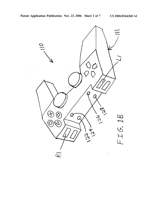
1. A controller, comprising: a body; one or more buttons disposed on the body; and one or more light-emitting diodes (LEDs) disposed on the body that are arranged in a geometric shape.
2. A controller in accordance with claim 1, wherein the one or more LEDs comprises four LEDs.
3. A controller in accordance with claim 1, wherein the geometric shape comprises a rectangle.
4. A controller in accordance with claim 1, wherein the one or more LEDs are attached to a front portion of the body that faces away from a user when the controller is properly held by the user.
5. A controller in accordance with claim 1, wherein the one or more LEDs are configured to be strobed.
6. A controller in accordance with claim 1, wherein the one or more LEDs are configured to be modulated.
7. A controller in accordance with claim 1, wherein the one or more LEDs are each configured to operate at a different frequency.
[0059] In step 304 the movements and deformities in the projection of the geometric shape are analyzed. Namely, the four dots of the bounding box are tracked and analyzed. Field and frame analysis is performed on the image plane of the camera output to analyze the manipulation of the four reference points to determine position orientation, tilt, yaw, roll, etc. of the controller. In addition, acceleration of the controller can be tracked in any direction. Analysis of the frames of the image can give the acceleration along any axis. Telemetry points of the controller can also be computed. It can also be determined whether or not the controller is in a resting position or resting state, such as for example when the controller is in a neutral or steady state near the user's waist.
[0060] As the controller rolls the image translates in the plane. Changes in the width of the rectangle of the bounding box indicate the controller is rolling. As the yaw of the controller is adjusted, the width of the rectangle changes. Yaw maps to the width of the rectangle. Tilt of the controller influences the height of the rectangle.
[0052] While the illustrated embodiment of the controller utilizes four LEDs, it should be well understood that other embodiments may utilize more than four LEDs or less than four LEDs. For example, three LEDs will work, and two LEDs will also work to provide tracking information. Even one LED can provide position information.
[0052] While the illustrated embodiment of the controller utilizes four LEDs, it should be well understood that other embodiments may utilize more than four LEDs or less than four LEDs. For example, three LEDs will work, and two LEDs will also work to provide tracking information. Even one LED can provide position information.
[0068] The image analyzer monitors the bounding box formed by the reference LEDs as captured in the image plane of the camera. The image analyzer analyzes the position, rotation, horizontal and vertical deformation of the bounding box to determine the physical user manipulation of the controller, its position, roll, tilt and yaw coordinates. At the end of the image analysis the data may be output in the form of an output ID or the like. Such output IDs from the image analysis may include data such as the x, y, z coordinates, acceleration and velocity along any axis, that the controller is in a resting position or state, etc. Thus, at the end of image analysis the image analyzer can indicate where the controller is and whether a command is issued. And the image analyzer may be pinged at any instant of time and it may provide position, orientation, last command, etc.
[0069] By way of example, the image analyzer may provide, but shall not be limited to providing the following outputs:
[0070] CONTROLLER POSITION (X, Y, Z coordinates);
[0071] CONTROLLER ORIENTATION alpha, beta, gamma (radians);
[0072] CONTROLLER X-AXIS VELOCITY;
[0073] CONTROLLER Y-AXIS VELOCITY;
[0074] CONTROLLER Z-AXIS VELOCITY;
[0075] CONTROLLER X-AXIS ACCELERATION;
[0076] CONTROLLER Y-AXIS ACCELERATION;
[0077] CONTROLLER Z-AXIS ACCELERATION;
[0078] RESTING POSITION OF STEADY STATE Y/N (at waist as described, but may be defined as any position);
[0079] TIME SINCE LAST STEADY STATE;
[0080] LAST GESTURE RECOGNIZED;
[0081] TIME LAST GESTURE RECOGNIZED; and
[0082] INTERRUPT ZERO-ACCELERATION POINT REACHED.
[0113] In addition to conventional features, the joystick controller 430 may include one or more inertial sensors 432, which may provide position and/or orientation information to the processor 401 via an inertial signal. Orientation information may include angular information such as a tilt, roll or yaw of the joystick controller 430. By way of example, the inertial sensors 432 may include any number and/or combination of accelerometers, gyroscopes or tilt sensors. In a preferred embodiment, the inertial sensors 432 include tilt sensors adapted to sense orientation of the joystick controller with respect to tilt and roll axes, a first accelerometer adapted to sense acceleration along a yaw axis and a second accelerometer adapted to sense angular acceleration with respect to the yaw axis. An accelerometer may be implemented, e.g., as a MEMS device including a mass mounted by one or more springs with sensors for sensing displacement of the mass relative to one or more directions. Signals from the sensors that are dependent on the displacement of the mass may be used to determine an acceleration of the joystick controller 430. Such techniques may be implemented by program code instructions 404 which may be stored in the memory 402 and executed by the processor 401.
[0114] By way of example an accelerometer suitable as the inertial sensor 432 may be a simple mass elastically coupled at three or four points to a frame, e.g., by springs. Pitch and roll axes lie in a plane that intersects the frame, which is mounted to the joystick controller 430. As the frame (and the joystick controller 430) rotates about pitch and roll axes the mass will displace under the influence of gravity and the springs will elongate or compress in a way that depends on the angle of pitch and/or roll. The displacement and of the mass can be sensed and converted to a signal that is dependent on the amount of pitch and/or roll. Angular acceleration about the yaw axis or linear acceleration along the yaw axis may also produce characteristic patterns of compression and/or elongation of the springs or motion of the mass that can be sensed and converted to signals that are dependent on the amount of angular or linear acceleration. Such an accelerometer device can measure tilt, roll angular acceleration about the yaw axis and linear acceleration along the yaw axis by tracking movement of the mass or compression and expansion forces of the springs. There are a number of different ways to track the position of the mass and/or or the forces exerted on it, including resistive strain gauge material, photonic sensors, magnetic sensors, hall-effect devices, piezoelectric devices, capacitive sensors, and the like.
[0115] In addition, the joystick controller 430 may include one or more light sources 434, such as light emitting diodes (LEDs). The light sources 434 may be used to distinguish one controller from the other. For example one or more LEDs can accomplish this by flashing or holding an LED pattern code. By way of example, 5 LEDs can be provided on the joystick controller 430 in a linear or two-dimensional pattern. Although a linear array of LEDs is preferred, the LEDs may alternatively, be arranged in a rectangular pattern or an arcuate pattern to facilitate determination of an image plane of the LED array when analyzing an image of the LED pattern obtained by the image capture unit 423. Furthermore, the LED pattern codes may also be used to determine the positioning of the joystick controller 430 during game play. For instance, the LEDs can assist in identifying tilt, yaw and roll of the controllers. This detection pattern can assist in providing a better user/feel in games, such as aircraft flying games, etc. The image capture unit 423 may capture images containing the joystick controller 430 and light sources 434. Analysis of such images can determine the location and/or orientation of the joystick controller. Such analysis may be implemented by program code instructions 404 stored in the memory 402 and executed by the processor 401. To facilitate capture of images of the light sources 434 by the image capture unit 423, the light sources 434 may be placed on two or more different sides of the joystick controller 430, e.g., on the front and on the back (as shown in phantom). Such placement allows the image capture unit 423 to obtain images of the light sources 434 for different orientations of the joystick controller 430 depending on how the joystick controller 430 is held by a user.
[0116] In addition the light sources 434 may provide telemetry signals to the processor 401, e.g., in pulse code, amplitude modulation or frequency modulation format. Such telemetry signals may indicate which joystick buttons are being pressed and/or how hard such buttons are being pressed.


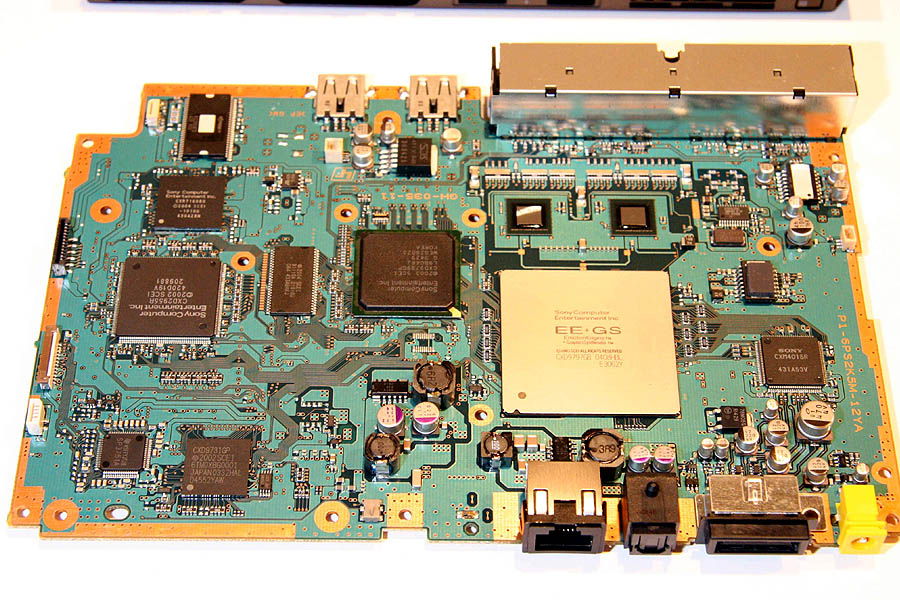
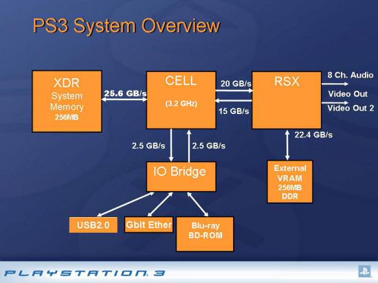 whopping 25.6 GB/s of bandwidth and to its left we can see the 35 GB/s connection (a 20 GB/s channel delivering data to RSX from CELL and a 15 GB/s channel delivering data from RSX to CELL) to the system Graphics Processor code-named RSX. You can see how Rambus's patented FlexPhase technology allows the data and multiplexed command+address traces to be laid out in a flexible and simple way (rest of PR speech is here ;)). The CPU code is CXD2964GB.